
6.3 Circuit Connection
2. Now, connect the components and make the robot assembly as instructed in the chapter-5.
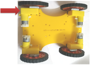
Note: Take the chassis and connect the motor clip with the Chassis then connect the motors on the clips.At the last attach the wheels as shown:
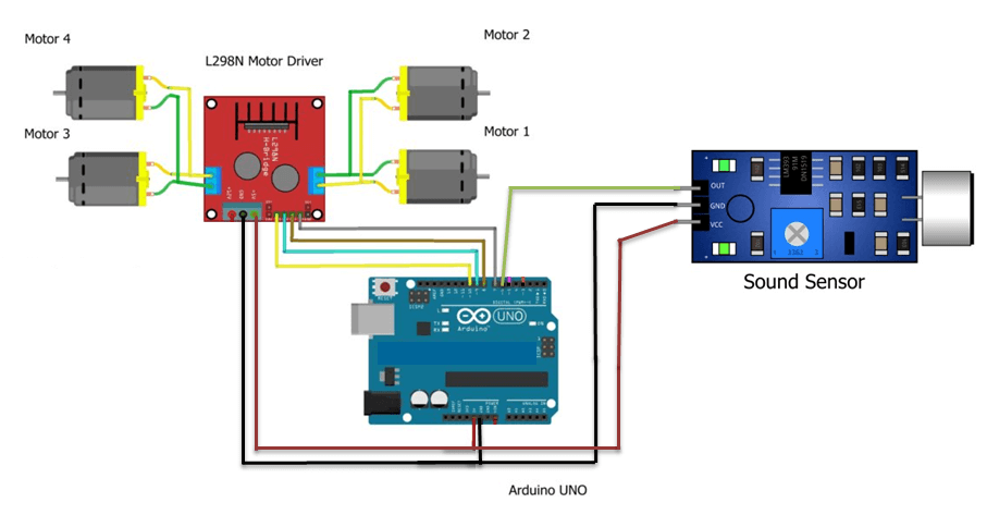
3. Now, connect the sound sensor module with Arduino Uno.
As, sound sensor module have 3 pins:
- VCC
- GND
- OUTPUT
4. Connect the VCC of sound sensor module with the +5V of Arduino Uno.
5. Connect the GND of sound sensor module with the GND of Arduino Uno.
6. Connect the OUT of sound sensor module with the digital pin 6 of Arduino Uno.
7. Now, connect all the 4 motors with Motor driver:
S.No. | MOTOR DRIVER | MOTORS |
1 | OUT2 | Positive (Red) of Motor 1 and 2 |
2 | OUT1 | Negative (Black) of Motor 1 and 2 |
3 | OUT4 | Positive (Red) of Motor 3 and 4 |
4 | OUT3 | Negative (Black) of Motor 3 and 4 |
8. Next, connect the motor driver with Arduino Uno:
MOTOR DRIVER | Arduino Uno |
IN1 | Digital Pin10 |
IN2 | Digital Pin9 |
IN3 | Digital Pin8 |
IN4 | Digital Pin7 |
5V | +5V |
GND | GND |