In this chapter, you will learn how to connect a RGB LED to the breadboard. Let’s start!
Components Required:
Breadboard
Battery
RGB LED
Resistor
Connecting wires.
Step 1: Open Tinkercad and select ‘Create new circuit’.
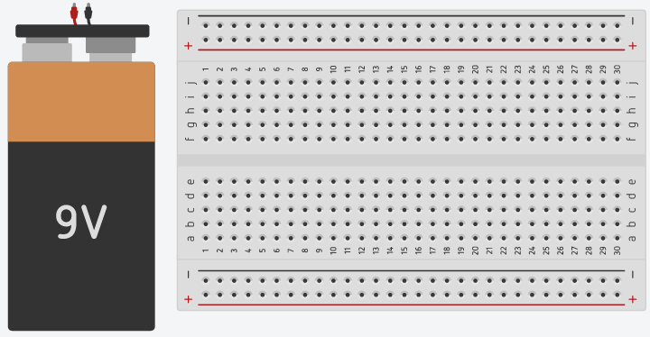
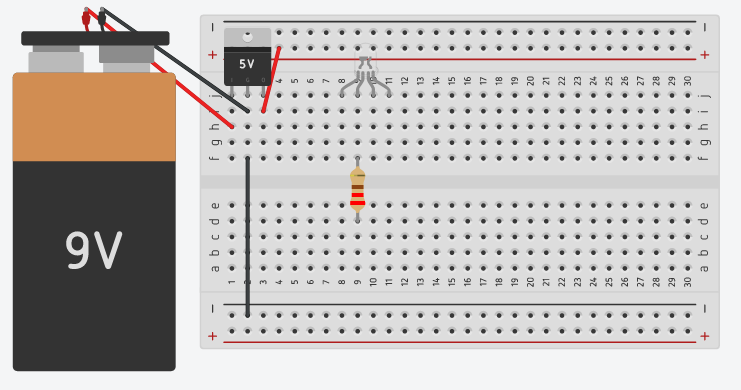
Step 2:Take out a breadboard and connect a battery as shown.
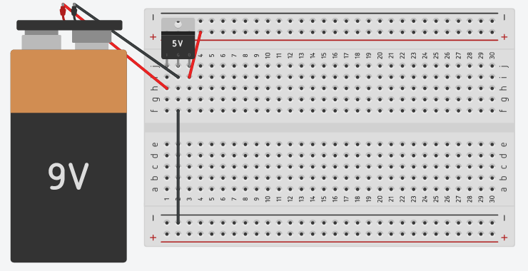
Step 3:Take out a 7805 voltage regulator and connect on the breadboard as shown.
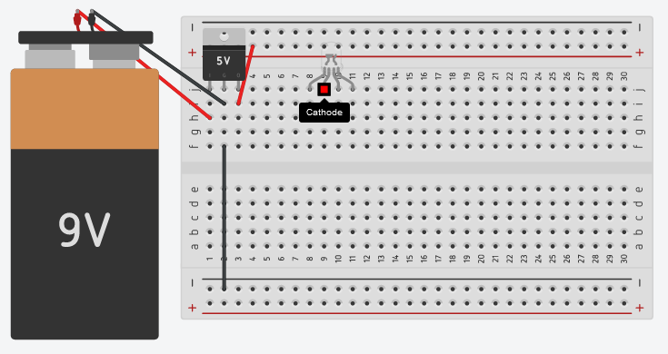
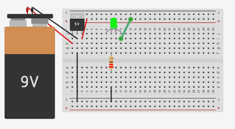
Step 4:Take out a RGB LED from components and place it on the breadboard as shown. Check it, either anode or cathode.
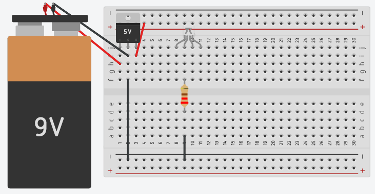
Step 5: For cathode, take out a resistor and place it as shown, to the cathode terminal of the RGB LED.
Step 6: Connect second end of the resistor to the ground rail of the breadboard.
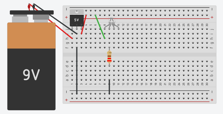
Step 7: Connect the first terminal of the RGB LED to the positive rail of the breadboard.
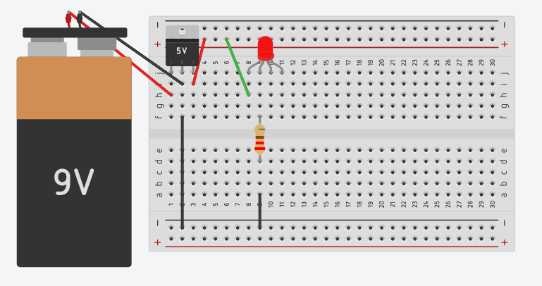
Click on ‘Start Simulation’.
As you can see, the LED will glow as Red.
Step 8: Click on ‘ Stop Simulation’.
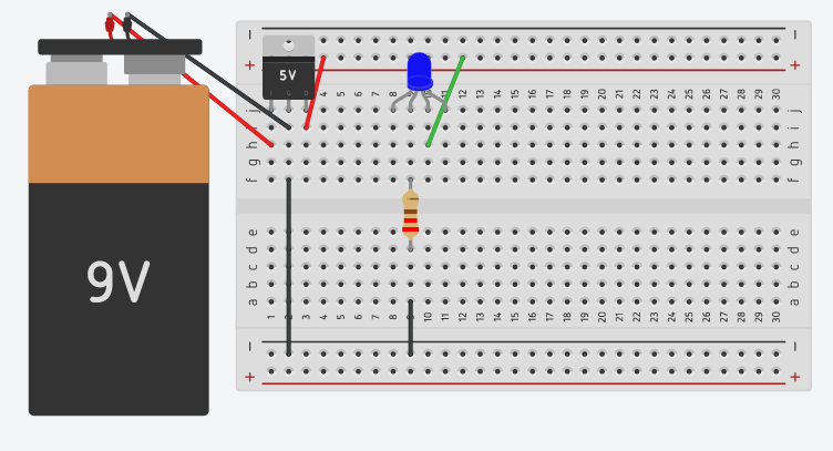
Step 9: Similarly, connect the other two terminals of RGB LED one by one, to see the other colors.
For Anode RGB LED, reverse the connections. The anode terminal will be connected to positive rail through the resistor and check every color by connecting the terminal to ground rail one by one.
Login
Accessing this course requires a login. Please enter your credentials below!