In this activity, you will learn about sensors. Let’s start!
Components Required:
Breadboard
Battery
Connecting Wires
LED
Resistor
LDR (Light Detecting Resistor)
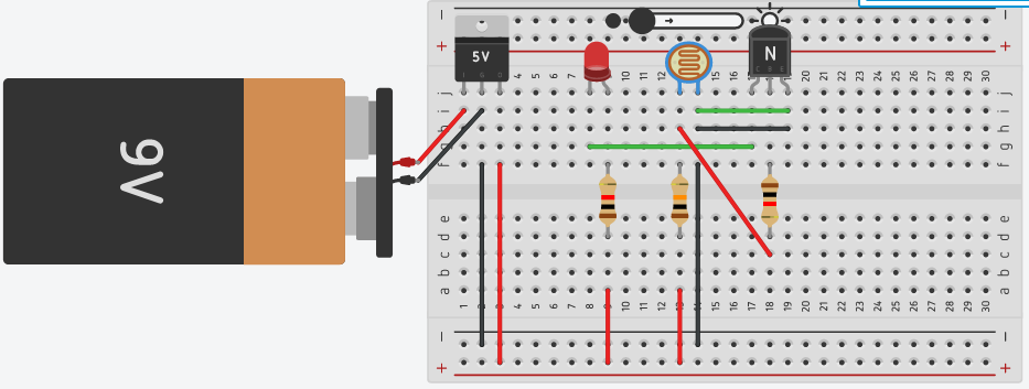
Circuit Simulation on bread board
This circuit can be used to automatically control and turn on-off lights or any loads depending on the brightness of ambient light.
To make this circuit, open Tinkercad and click on ‘Create new circuit’.
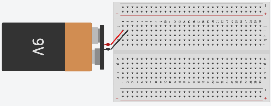
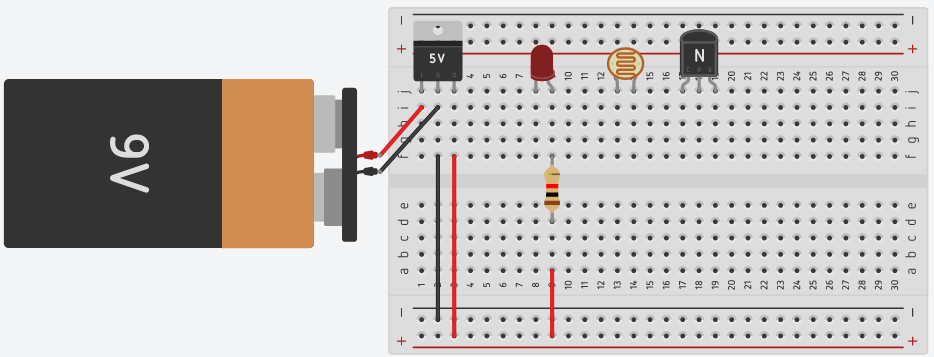
Step 1: Connect battery to the breadboard as shown.
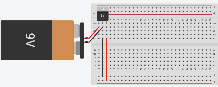
Step 2: Take out 7805 IC, connect as shown in figure below.
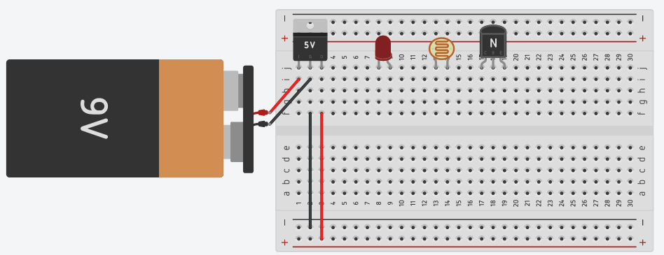
Step 3: Take a LED, photoresistor (LDR) and NPN transistor, place it on the breadboard.
We can make a transistor switch power to a load depending upon the light conditions. Simple transistor circuits with LDR are very common and utilized in night lighting and emergency lighting systems
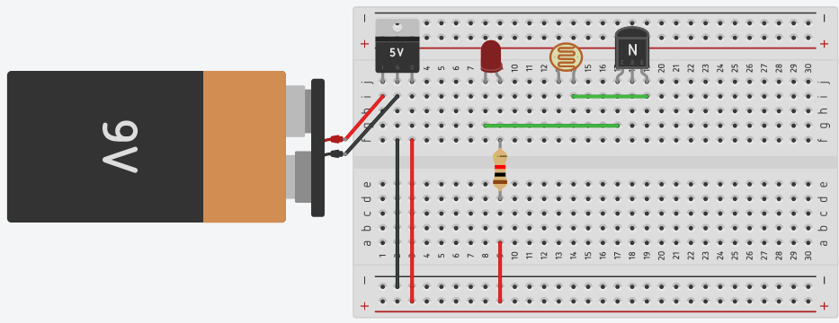
Step 4: Take a 1KOhm resistor and place its one end to the long lead of LED, another end to the positive rail of the breadboard.
Step 5: Connect emitter terminal of transistor to terminal 2 of LDR. Also connect collector terminal of transistor to negative terminal of LED.
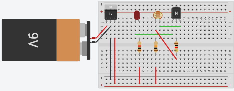
Step 6: Take 10KOhm resistor, place it between terminal 1 of LDR and positive supply. Also take another 1KOhm resistor between the base of transistor and terminal 1 of LDR.
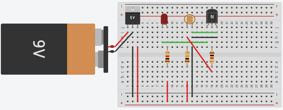
Step 7: Connect the emitter terminal of transistor to terminal 2 of LDR. Also connect terminal 2 of LDR to ground.
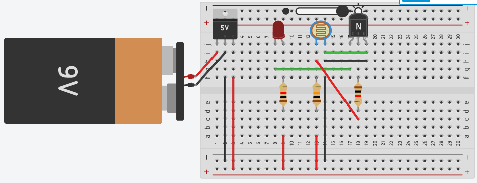
Step 8: Click on Start simulation. After this click on LDR, a slider will open.
As you can see slider showing day and night values. In night the LED will glow but when you move the slider towards the day the LED gradually starts dimming.
Login
Accessing this course requires a login. Please enter your credentials below!