This article explains the circuit design for blinking LED using a 555 timer IC. This is a simple circuit designed to explain the working and use of a 555 timer IC.
Component Required:
555 timer IC
LED
Battery
1KΩ Resistor – 2
470KΩ Resistor
1µF Capacitor
Bread Board
Connecting wires
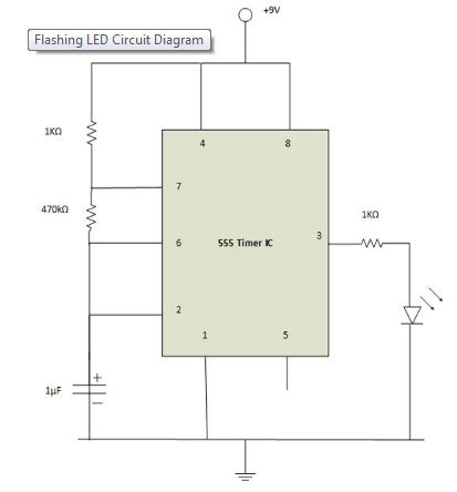
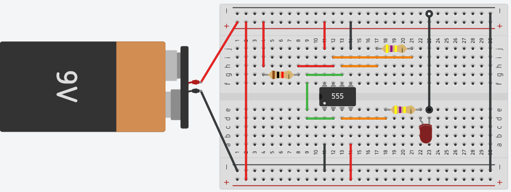
Circuit Diagram
The following circuit design explains the design of the blinking LED (Light Emitting Diode) with the 555 timer IC. Here in this configuration, the 555 timer IC has connected in an Astable mode of 555 timer operation.
Steps to follow:
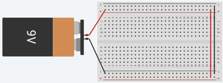
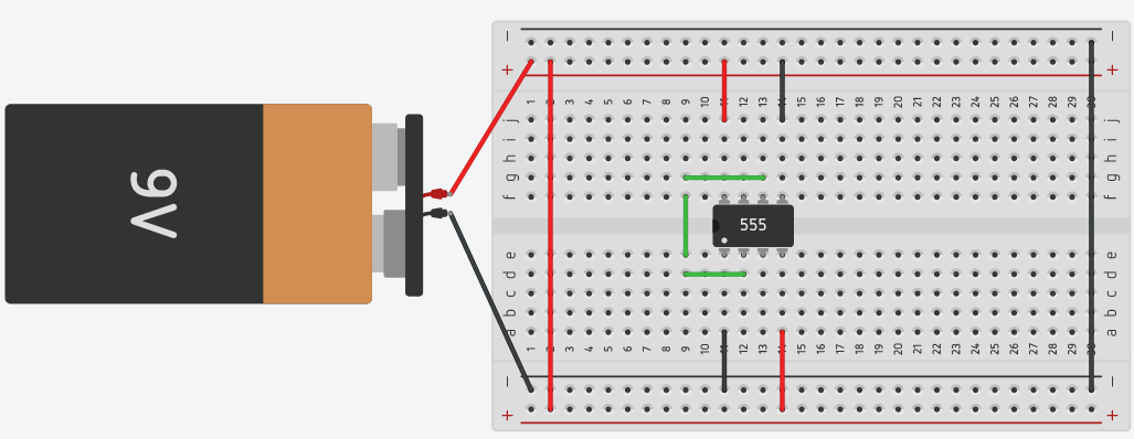
Step 1: Open Tinkercad and click on ‘Create new circuit’.
Step 2: Connect battery to the circuit as shown.
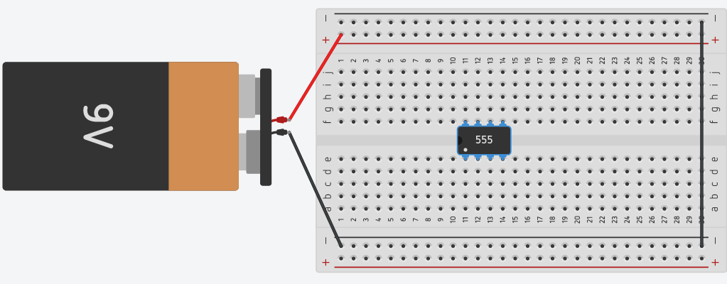
Step 3: Collect all the required components and place the 555 timer IC on the breadboard.
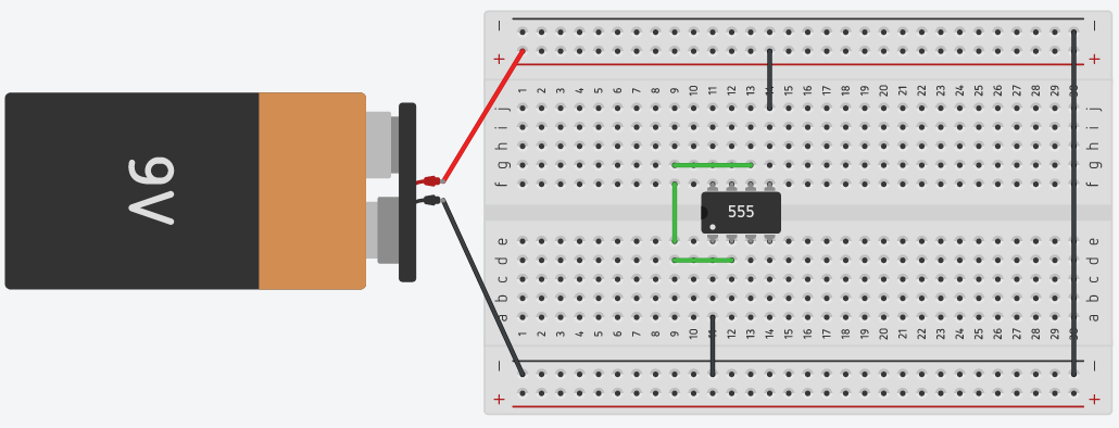
Step 4: Connect pin 1 and pin 5 of a 555 timer IC to the ground. You can find the pin structure of a 555 timer IC in the circuit diagram shown above.
Step 5: Now short the pin 2 to pin 6 of the 555 timer IC.
Step 6: Connect pin 4 and pin 8 to the positive rail of the breadboard.
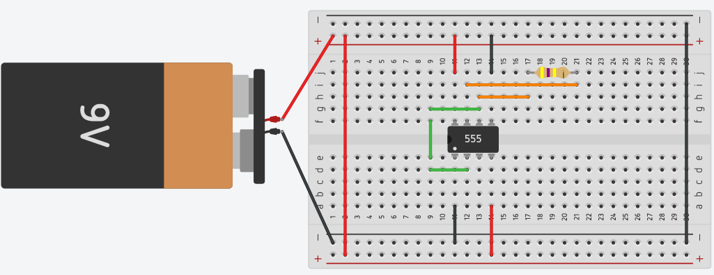
Step 7: Connect pin 6 to pin 7 using a 470kΩ resistor.
Step 8: Connect pin 7 to the positive end of the breadboard using a 1kΩ resistor.
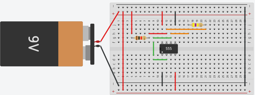
Step 9: Connect the output pin 3 with the positive lead of the LED using a 1kΩ resistor.
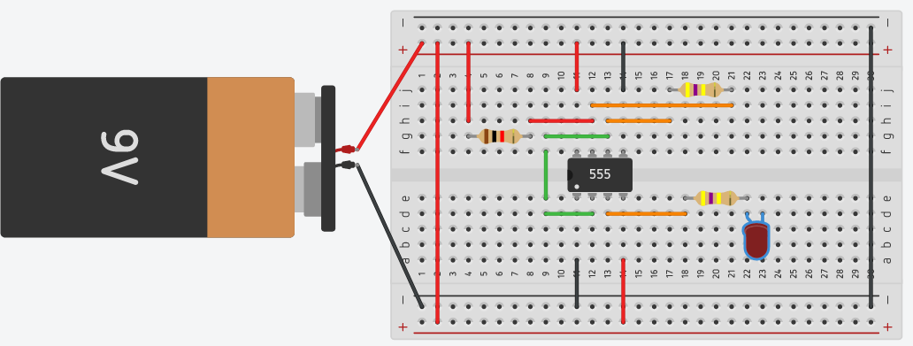
Step 10: The negative lead of LED needs to be connected with the ground rail.
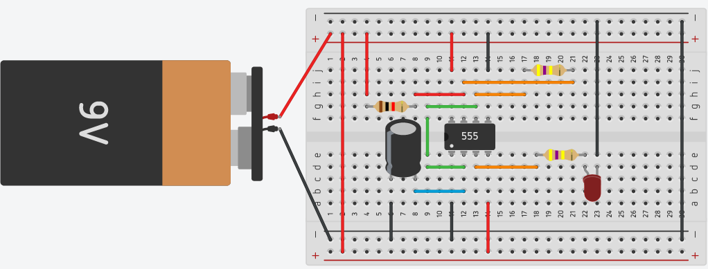
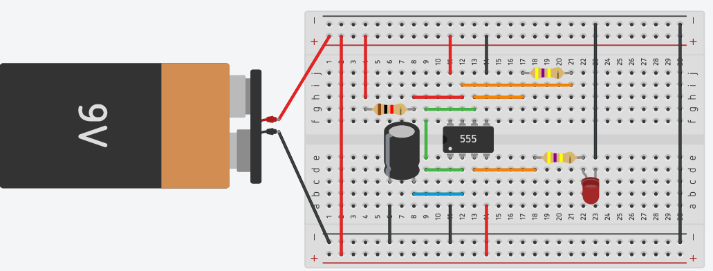
Step 11:The longer lead of a polarized capacitor is the positive and the shorter lead is negative. Connect pin 2 to the positive end of a capacitor. Connect the negative lead of the capacitor to the ground of the battery.
Step 12: Click on ‘Start Simulation’ and the LED will start to blink.