
Project: Logic Gate with LED and Sound
Logic gate with LED and Sound
The components required for this project are:
Power – 1
Push button – 1
Bright LED – 1
Buzzer – 1
Power junction – 1
NOT gate – 1
CT2 – 12
Gray Plate – 1
USB to DC jack – 1
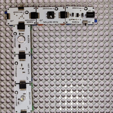
Circuit Connection :
Let’s start with the circuit.
First take a Power block and attach a Push-button to it.
On the other end of the Push button attach a power junction.
Join an LED on one end of the Power junction.
Now plug a NOT gate to the other end of Bright LED.
And lastly add the second Bright LED.
Now attach the CT2 connector at the bottom and Mount the circuit on the gray plate
- Power the circuit using the Power bank and USB to DC Jack.
Did you see that the Bright LED 2 is glowing even when the pushbutton is OFF? Now press the push button and see what happens.
Now press the Pushbutton. You can see that the Bright LED 1 is now ON and Bright LED 2 is turned OFF.
Now stop pressing the push button. You can see that the Bright LED 2 will turn ON and Bright LED 1 will be turned OFF. Try pressing the push button alternatively.
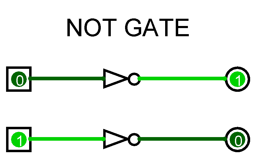
Did you observe the pattern in which Bright LED 1 and 2 are glowing? They glow in an alternate manner. This is how a NOT gate works. Bright LED 1 is the actual output we require from the circuit. But since we have used a NOT gate before Bright LED 2, the output received from the Bright LED 2 is inverted.
In this way you have inverted the output of the Pushbutton, which now turns the Bright LED 2 when pressed. NOT gates are used internally in almost all the digital electronics we use!