
Project: Parallel Connection of POT and Switch
Parallel connection of Potentiometer and Switch

Let’s see in the below project how a parallel connection works.
In this project, let’s try to control a LED and a Buzzer in a parallel connection.
Component Required:
Components required for this project are:
Power block – 1
Power junction – 1
Push Button – 1
Potentiometer – 1
Bright LED – 1
Buzzer -1
Power bank – 1
USB to DC jack – 1
Circuit Connection:
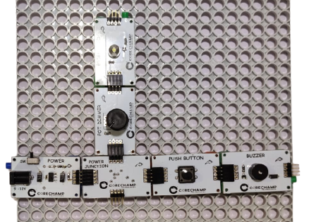
Now let’s start with the circuit.
First, take the power block and join a Power junction.
Now plug two Pushbutton into the power junction and one Buzzer to it as shown.
Now add a POT and Bright LED to the other end of Power junction.
At last attach the CT2 connector at the bottom of all the Mini PCBs.
And mount the circuit on the Gray plate.
Let’s try the circuit.
Turn ON the power supply.
You will see that You can only control the Buzzer with the Pushbutton and POT will only control the Bright LED.
This is how a parallel connection works.
Do it yourself :
Try replacing the Bright LED with the Buzzer and motor and see what happens.