

SCHEMATIC SYMBOLS
SCHEMATIC SYMBOL
Electronic component symbols are used to denote the components in circuit diagrams. There are standard symbols for each of the components which represent that particular component.
RESISTORS
The most fundamental of circuit components and symbols! Resistors on a schematic are usually represented by a few zig-zag lines, with two terminals extending outward. Schematics using international symbols may instead use a featureless rectangle, instead of the squiggles.
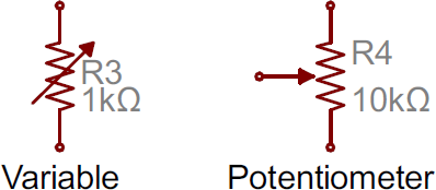
Potentiometers and Variable Resistors
Variable resistors and potentiometers each augment the standard resistor symbol with an arrow. The variable resistor remains a two-terminal device, so the arrow is just laid diagonally across the middle. A potentiometer is a three-terminal device, so the arrow becomes the third terminal (the wiper).
Capacitors
There are two commonly used capacitor symbols. One symbol represents a polarized (usually electrolytic or tantalum) capacitor, and the other is for non-polarized caps. In each case there are two terminals, running perpendicularly into plates.
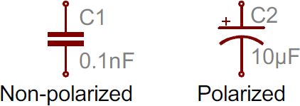
The symbol with one curved plate indicates that the capacitor is polarized. The curved plate usually represents the cathode of the capacitor, which should be at a lower voltage than the positive, anode pin. A plus sign should also be added to the positive pin of the polarized capacitor symbol.
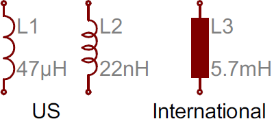
Inductors
Inductors are usually represented by either a series of curved bumps, or loopy coils. International symbols may just define an inductor as a filled-in rectangle.
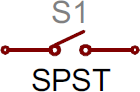
Switches
Switches exist in many different forms. The most basic switch, a single-pole/single-throw (SPST), is two terminals with a half-connected line representing the actuator (the part that connects the terminals together).
Switches with more than one throw, like the SPDT and SP3T below, add more landing spots for the the actuator.
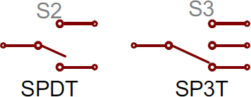
Switches with multiple poles, usually have multiple, alike switches with a dotted line intersecting the middle actuator.
Power Sources
Just as there are many options out there for powering your project, there are a wide variety of power source circuit symbols to help specify the power source.
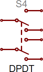
DC or AC Voltage Sources
Most of the time when working with electronics, you’ll be using constant voltage sources. We can use either of these two symbols to define whether the source is supplying direct current (DC) or alternating current (AC):
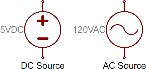
Batteries
Batteries, whether they’re those cylindrical, alkaline AA’s or rechargeable lithium-polymers, usually look like a pair of disproportionate, parallel lines:
More pairs of lines usually indicates more series cells in the battery. Also, the longer line is usually used to represent the positive terminal, while the shorter line connects to the negative terminal.
Voltage Nodes
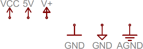
Sometimes — on really busy schematics especially — you can assign special symbols to node voltages. You can connect devices to these one-terminal symbols, and it’ll be tied directly to 5V, 3.3V, VCC, or GND (ground). Positive voltage nodes are usually indicated by an arrow pointing up, while ground nodes usually involve one to three flat lines (or sometimes a down-pointing arrow or triangle).
Schematic Symbols (Part 2)
Diodes
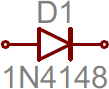
Basic diodes are usually represented with a triangle pressed up against a line. Diodes are also polarized, so each of the two terminals require distinguishing identifiers. The positive, anode is the terminal running into the flat edge of the triangle. The negative, cathode extends out of the line in the symbol (think of it as a – sign).
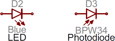
There are a all sorts of different types of diodes, each of which has a special riff on the standard diode symbol. Light-emitting diodes (LEDs) augment the diode symbol with a couple lines pointing away. Photodiodes, which generate energy from light (basically, tiny solar cells), flip the arrows around and point them toward the diode.
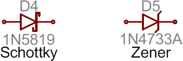
Other special types of diodes, like Schottky’s or zeners, have their own symbols, with slight variations on the bar part of the symbol.
Transistors
Transistors, whether they’re BJTs or MOSFETs, can exist in two configurations: positively doped, or negatively doped. So for each of these types of transistor, there are at least two ways to draw it.
Bipolar Junction Transistors (BJTs)
BJTs are three-terminal devices; they have a collector (C), emitter (E), and a base (B). There are two types of BJTs — NPNs and PNPs — and each has its own unique symbol.
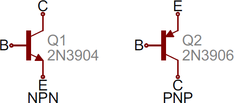
The collector (C) and emitter (E) pins are both in-line with each other, but the emitter should always have an arrow on it. If the arrow is pointing inward, it’s a PNP, and, if the arrow is pointing outward, it’s an NPN. A mnemonic for remembering which is which is “NPN: not pointing in.”
Metal Oxide Field-Effect Transistors (MOSFETs)
Like BJTs, MOSFETs have three terminals, but this time they’re named source (S), drain (D), and gate (G). And again, there are two different versions of the symbol, depending on whether you’ve got an n-channel or p-channel MOSFET. There are a number of commonly used symbols for each of the MOSFET types:
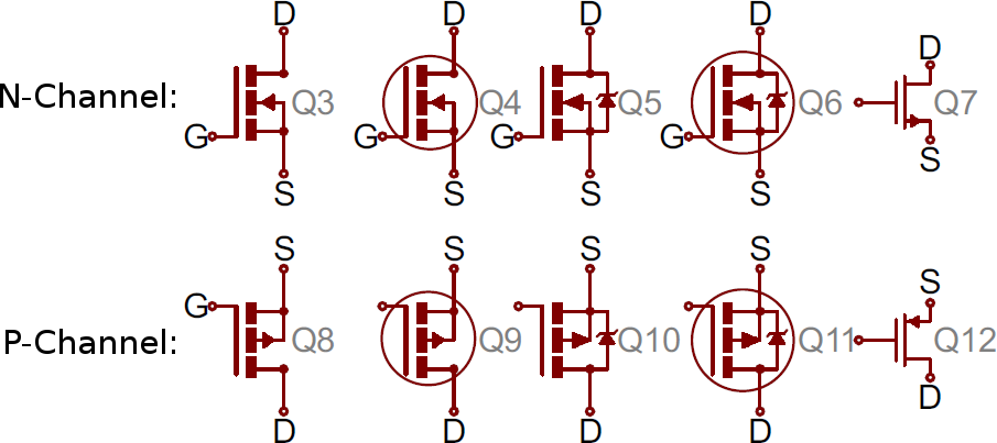
The arrow in the middle of the symbol (called the bulk) defines whether the MOSFET is n-channel or p-channel. If the arrow is pointing in means it’s a n-channel MOSFET, and if it’s pointing out it’s a p-channel. Remember: “n is in” (kind of the opposite of the NPN mnemonic).
Digital Logic Gates
Our standard logic functions — AND, OR, NOT, and XOR — all have unique schematic symbols:

Adding a bubble to the output negates the function, creating NANDs, NORs, and XNORs:

They may have more than two inputs, but the shapes should remain the same (well, maybe a bit bigger), and there should still only be one output.
Integrated Circuits
Integrated circuits accomplish such unique tasks, and are so numerous, that they don’t really get a unique circuit symbol. Usually, an integrated circuit is represented by a rectangle, with pins extending out of the sides. Each pin should be labeled with both a number, and a function.
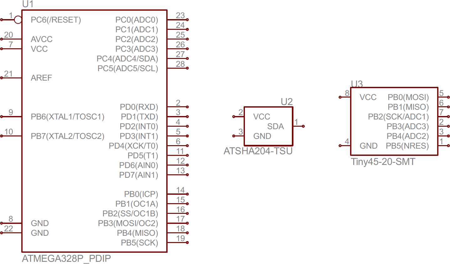
Because ICs have such a generic circuit symbol, the names, values and labels become very important. Each IC should have a value precisely identifying the name of the chip.
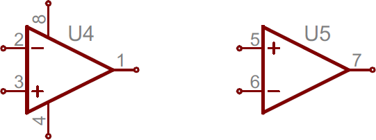
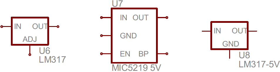
Unique ICs: Op Amps, Voltage Regulators
Some of the more common integrated circuits do get a unique circuit symbol. You’ll usually see operation amplifiers laid out like below, with 5 total terminals: a non-inverting input (+), inverting input (-), output, and two power inputs.
Simple voltage regulators are usually three-terminal components with input, output and ground (or adjust) pins. These usually take the shape of a rectangle with pins on the left (input), right (output) and bottom (ground/adjust).
Miscellany
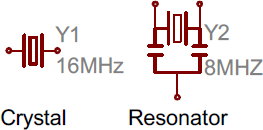
Crystals and Resonators
Crystals or resonators are usually a critical part of microcontroller circuits. They help provide a clock signal. Crystal symbols usually have two terminals, while resonators, which add two capacitors to the crystal, usually have three terminals.
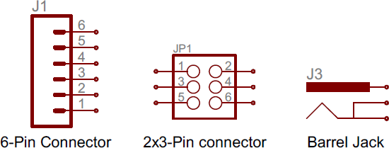
Headers and Connectors
Whether it’s for providing power, or sending out information, connectors are a requirement on most circuits. These symbols vary depending on what the connector looks like, here’s a sampling:
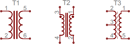
Motors, Transformers, Speakers, and Relays
We’ll lump these together, since they (mostly) all make use of coils in some way. Transformers (not the more-than-meets-the-eye kind) usually involve two coils, butted up against each other, with a couple lines separating them:
Relays usually pair a coil with a switch:

Speakers and buzzers usually take a form similar to their real-life counterparts:

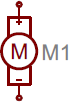
And motors generally involve an encircled “M”, sometimes with a bit more embellishment around the terminals:
Fuses and PTCs
Fuses and PTCs — devices which are generally used to limit large inrushes of current — each have their own unique symbol:
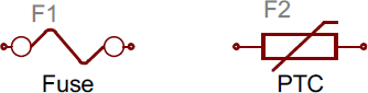
The PTC symbol is actually the generic symbol for a thermistor, a temperature-dependent resistor (notice the international resistor symbol in there?).