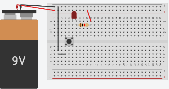
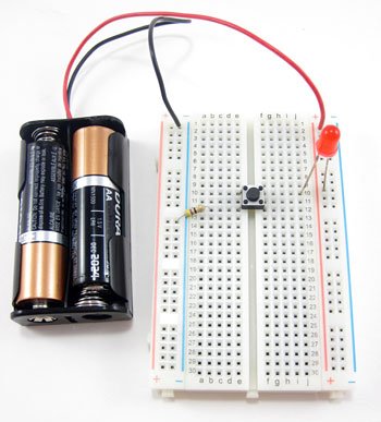
A breadboard diagram is a computer-generated drawing of a circuit on a breadboard. Unlike a circuit diagram or a schematic (which use symbols to represent electronic components), breadboard diagrams make it easy for beginners to follow instructions to build a circuit because they are designed to look like the “real thing.” For example, this diagram (made with a free program called Tinkercad) shows a basic circuit with a battery pack, an LED, a resistor, and a pushbutton, which looks very similar to the physical circuit.
Sometimes, breadboard diagrams might be accompanied by (or replaced with) written directions that tell you where to put each component on the breadboard. For example, the directions for this circuit might say:
Connect the battery’s red lead to the power bus.
Connect the battery’s black lead to the ground bus.
Connect the resistor from hole A11 to the power bus.
Insert the push-button’s four pins into holes E6, F6, E8, and F8.
Insert the LED’s long lead into the hole C11, and the short lead into hole C10.
Connect hole A8 and A10.
Connect one end of push-button to ground bus.
Does my circuit have to match the breadboard diagram exactly?
The answer is “no.” However, when you are first starting out using breadboards, it is probably best to follow the breadboard diagrams exactly.
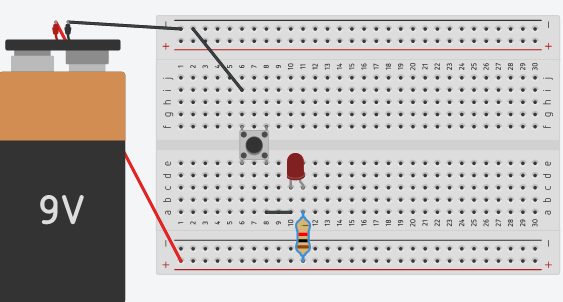
It helps to understand how a breadboard’s holes are electrically connected. There are different ways to change the physical layout of a circuit on a breadboard without actually changing the electrical connections.
For example, these two circuits are electrically identical; even though the leads of the LED have moved, there is still a complete path for electricity to flow through the LED. So, even if the directions of the components changed, the circuit will still work.